Sunday, January 27, 2013

DAY 20 - Has it really been two weeks ???

Missed working last weekend - something about a red-eye return on Saturday Morning and leaving on Sunday makes for short time at home.

I certainly made up for it in new "stuff".  I find it difficult to think about anything but what I want to work on next as I sit in some random hotel room during the week.  This is good and bad - I play out all of the options in my head - my inner dialog argues the good and bad points about what I want to do.

Bad : as I think of something - I usually get online and order parts.  Two days later, I think of / read about something different, and decide to go in a different direction.  Admittedly, this has slowed down the progress of the build, but it has also offered me insights on the advantages and disadvantages of certain building methods.

Good : When I do get home, I have a host of stuff to tear into.  Most times, I do remember everything I have ordered.  More important, I remember what I was thinking when I ordered it.

At any given time on  the Astromech boards, members offer parts for sale.  These parts are either from a Builder's Council approved "run" or they are members selling extras that they don't need.  Typically, the official runs of parts require you to get on a list and wait until the parts are made.  This can take a couple of weeks to a few months to complete.  When a member offers parts for sale from their private stock, it is sometimes funny to watch how quickly the parts are scooped up.  I have seen parts sell 30 seconds after they are posted "for sale".  This is especially true when aluminum details become available.  I have been fortunate to grab a good number of pieces second hand along the way.  The members are always excellent with their communication, and I have no qualms about sending money for parts listed on the forums.

I thank Mom and Dad for all of the effort they have put in on this project - between monitoring and receiving nearly daily visits from the USPS to dealing with the random bits of aluminum dust floating about the basement.

Mom likes to inform me of just how many packages arrived on any given week.  I believe this week (In my defense, it was actually 2 weeks) the count was 19.  Nylon Lock nuts, Captive Studs, Motor Mount Tensioners... and.... uhhhhh, I don't know what else.  That said, here is the pile of goodies I came home to this weekend:


In earlier posts, I had talked about my concern about the long-term resilience of some of the styrene / ABS / Acrylic parts on my oh so weight-unconscious friend.  One of the main concerns was (and to some point is) the legs and feet.  When it all breaks down, the entire weight of the droid is supported at three points: The two outer ankles and center leg.  There are 1/2" bolts on the outer legs and a 3/8" bolt in the center leg that attaches the motor mount and caster assemblies to the bottom of the leg.  That is a lot of weight on these three points.

Steele and Ted, two outstanding members of the Atlanta-based R2 Builders Club, are a couple of guys that like to make parts available to members of the Astromech community.  Steele and Ted are the ones who put together the run of the blue anodized dome base plates a couple of months back.  The really cool thing about the boards is when a member comes up with a new solution, you can either A: try to recreate it with your own modifications or B: Pray that the member turns it into a "run".  Ted had mentioned this run becoming a possibility a couple of months ago.  I toyed with the idea of making my own motor mounts out of 3" x 4" square aluminum tube.  "Toyed" meaning, actually bought the tube on eBay.... then decided that I like sound of "Water Jet Cut Aluminum Plates - All hardware included" that was offered when the run became a reality.  

Here is what the kit looks like out of the box.  I think my favorite part is the "Hardware Burrito Pack".  This had all of the nuts, bolts and spacers individually bagged and labeled for easy reference along with the 20 page instruction manual.  The bag of bolts did look like a burrito, enough to make Chipotle jealous.  I imagine consuming this burrito would be slightly more kind to your stomach then those that come wrapped in aluminum foil.


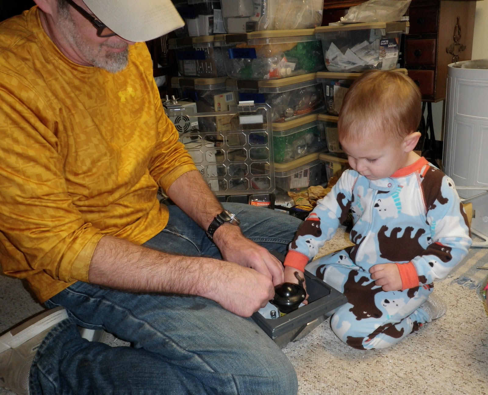
As with most of the photos I take, they are of the complete project... no time for fancy picture takin' when you are working.  Dad and I sat down with one foot each and got to task. 

What are the advantages of these mounts ?

     - Aluminum (duh) no worries about strength
     - Axle tensioner that pulls on Aluminum plate
     - The moter mounts directly to the aluminum plate - no play or wiggles to worry about.
     - Aluminum center channel mount.  The ankle bolt is threaded into the channel....awesome. 
     - Swivel casters.  Although I really like the Uniball casters, I have seen too many reports of other
       members swapping them out for traditional swivel casters.  The Uniballs are not cheap and are
       only available from a supplier in the U.K.


The other side.  Mmmmmmmm - water jet cut aluminum......


Top view of the motor mount.  After these were all assembled - Dad and I were congratulating each other on a fine job.... then we tried to put them in the foot shells.  

The center channel on the motor mount was too narrow to fit inside the foot.  This was rectified by placing spacers in the center channel to widen the gap.  Dad said something about "tight tolerances" - yeah you bet.  These things fit together one way and one way only - not much room for creativity here.


Hmmmm... last post, nephew Kaden was "helping" Uncle Dott.  Here is Daddy-O HELPING his boy. It was a good day, and R2 has new insoles that I trust in supporting his weight.


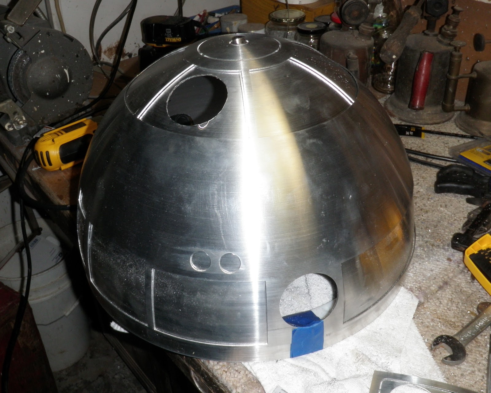
Yet another left turn in the build.  More Aluminum stuff bought second-hand from a member of the Astromech boards.  Below is what is known as a 300mm aluminum dome.   These come with an inner dome that is uncut and an outer dome that is LASER cut.   Pffffffft... water jet..... we gots LASERS !  Both methods produce excellent precision cuts.  The outer dome is a thing of beauty.  All of the details cut with excellent precision, all you need to do is use a hack-saw and cut off 1/16" tabs that hold the panels in place.


Cutting the panels off took a total of about 10 minutes.  Then it came time to address the inner dome.  I started with what I thought was going to be the difficult part - cutting the holes for the holo-projectors.  Turns out this was the easy part.

First, mark the hole and drill a series of holes around the perimeter of the hole.  (Not sure if I could have used the word "hole" one more time in that sentence)


I had read a number of posts about scoring pizza like pie cuts in the center of the hole and then snapping the parts out.  I opted to try using the Roto-Zip bit on these.  Here is a short video showing the process.


A shot of the dome with the holo-ports cut in the inner dome.


Next came the rather difficult process of cutting the access windows for the top pie panels.  Who knew that cutting a circle would be infinitely easier than cutting a number of straight lines ?  Not this guy, until it was done.  


I ended up using a combination of techniques to achieve my goal.  What I found to work the best was to score the dome alone the cut line with a metal cutting disk on the Dremel.  Then I drilled a couple of holes in the score line.


Next, I switched back to the Dremel metal cut-off disk and cut through the area where I drilled the holes.  (Less material - easier cut).  Finally, I used a Skil-saw to saw the final line.  Unfortunately, I developed this successful technique on the second to last pie panel, so I had a TON of filing to do on the other cuts to make then straight.


The interesting thing about the Aluminum Domes is that the inner and outer domes do not seat perfectly together.  Some members report "getting lucky" and receiving domes that seat together perfectly, but from what I understand, they are few and far between.   When the inner and outer dome were set together, there was about a 1/8" gap at the pie panels and 1/4" gap at the bottom.  This is not good, as the inner dome needs to sit flush against the outer dome in order for the panels and doors to sit properly.

A quick search on the boards let me know how to resolve this issue.  Cut the inner dome.  Just the thought of this made my lower region pucker a bit.  Well, the Lord hates a coward, so off to the chopping block, inner dome.  I decided that a better fit would be achieved by cutting the top portion and bottom portion separately.


Once this was done, it made me feel much better about the surgery I just performed.  You can see the split in the upper left hand corner in the top and bottom sections of the inner dome.  Note the gap near the holo-projector hole in the upper left.  There was just too much play in the dome without resulting to these cuts.  The top pie panels sit perfectly now (although there are no photos) and once the inner and outer domes are bonded together, the recesses for the doors will be perfect all the way around.


Sunday at around 5:00, my hands finally gave out, I was finding it difficult to grasp a file.  A combination of cramping and metal shavings finally put this builder to rest.  

More on the dome progress in upcoming installments.  I am very excited to get this in place on R2's head !

Oh, and another goody that arrived this week.  Electromagnetic charge arm for zapping Buzz-Droids !  This photo is courtesy of Astromech member Rotopod's post, mine will be assembled soon.  Apparently, you can "age" the bronze piece by soaking it in vinegar and placing it in the oven at 475 degrees for 15 minutes.  I am sure Mom will be happy to let me do that in her new oven.  Heck - there are 2 - if it ruins one, there is a spare.... right ?!?!?


Sunday, January 13, 2013

DAY 19 - Baby needs new shoes and a little help from the little one.

Another week of packages, and other day of building.  This week, I received some outstanding parts from Oscar (Zhunter) on the Astromech boards.  Some Aluminum Ankle Cylinders, wedges and holders.  I also received my 24 volt battery tender, some various Arduino boards and other stuff that I can't recall a short day after I opened them up.

Mom asked me, "How can you remember what you have ? Have you ordered something twice ?"

I replied, "I think I have ordered more paint than I need...."  The truth is, I have ordered more than a few things twice.  Sometimes to round out a set of something, and more often than not, because I have forgotten that I already have two (or more) sitting in a bin.  

For the most part, the duplicates are redundant items that I have collected in my effort to upgrade to all aluminum details.  At times, when parts come available on the Astromech parts junkyard, they are not complete sets.  In particular, I had two aluminum ankle cylinders that I bought second hand from a member.  Later, the ankle cylinder run came up, and I ordered a full set of 4, so that leaved me with two extra.  The great thing about these extra parts, is the fact that they can be used as spares, they can readily be sold to other members, or they can be used on a second droid.  After all, what am I going to do with all of my time once this guy is finished ?  The obvious answer is FISH, but a man has to keep his options open.

So on to the progress form this day of work.  It was all about the feet today.  I purchased a set of JAG steel feet from BobC who got them from another member on the boards.  One of the many suggestions when using the A&A acrylic motor holders is to bolster them up a bit, as the holders were designed to support a (mostly) PVC and ABS droid.

As I add more and more metal to the frame, legs and dome, the poor feet have to bear the brunt of all this added weight.

After a week of sitting on the center leg, caster bracket already showed signs of warping.  The wood blocks shown below are used as stand-offs to support the weight of the droid on the center foot.


Here is the topside view.  Screw-crazy, I know - but it works, and the center foot is extremely happy now with it's added support system.


Here are the outer foot shells after a good bit of re-work.  A couple of issues that were resolved :  The detail pieces in the lower left and right were too close to the center.  When the Half-moon detail was put on, it was practically touching the detail pieces.  The detail pieces were removed and re-drilled and placed in a position more to my liking.  I did manage to snap one of the bolts on two of the detail pieces while removing them, so I had to re-fit it with a screw (seen in the lower right).  A little bit of bondo and paint, and it will look right as rain.  One of the feet also had the top horizontal strip on upside down.... ?  That was rectified, and the results are shown in the photos below.


Another (minor) issue with the feet.  As these were used on a droid in a previous life, the holes were already cut out and expanded to allow access to the scooter motors.  Last week, I put the feet in the legs and left the setup as it was.  For the uninitiated, there is a front and back to the feet.  The front has a mount for the knurled hose fittings and hoses that extend to the battery boxes.  This mount was already in place, as was the strip with the associated holes drilled in it.  Again, I put the scooter motor holders in the feet as per the previous setup.  The only problem was that the drive wheel was in the front, and the caster was in the back.  The video posted last week showed the foot "kicking up" a couple of times, this was because the drive wheel was in front, and the center of gravity was not centered on the entire foot, only on the drive wheel.

Duh - so why don't you just put the left foot on the right, and vice versa ????  Well, the battery box cutout allows the battery box to go on in one direction.  So - to flip the foot drive around, I had to drill out new access holes for the hose fittings.

Here is where I got to use my Unibit Step Drill Bit.  These things are not cheap, but once in the drill press, they cut through aluminum and steel like butter.  This bit was originally purchased to drill the holes in the aluminum blocks for the center foot riser.

Another angle of the outer foot shell with the half moon details installed.


Once the feet were oriented in the correct direction, it came time to mount the battery boxes.  These boxes are of the PVC flavor - quite nice and quite light.  A couple of screws in the right place, slip into the pre-drilled key slots....


Front view of the foot with the battery box.  The screws in the top channel are used to bolt the motor holders to the outer foot.  There are additional bolts that hold the scooter motor assembly on the side behind the battery box.  The knurled hose fitting strip is a little bit off, and looks MUCH worse in this photo because of the angle.  I will most likely make a new set of mounts out of a couple of pieces of aluminum.


One more angle of the shoes.


I think I may have been a little overzealous by getting R2 to walk so early.  Now all I want to do it wire him up, and rill him around.  Brother Kris saw the video, and wanted to see it in person, so I re-wired all of the power (which was sitting in a bin).  I am glad to have this exercise, because with each re-wire and tear-down, I get more familiar with what I do and don't need to do when I finally assemble the final power matrix.

In this go-round, I ran the foot wires through the access channels in the legs.  I know, taping the to the sides was cool and all.. but this is the way it has to be done.


Peeking out through the hub at the top of the leg.  You can see where I epoxied the lag bolts into the leg.  I am not 100% sure that this was the best idea, but there it is in all it's two-part-quick-set goodness.


The bottom of the leg showing the ankle modification where the holes were dropped to allow the feet to sit at the correct angle.  Oak dowel/plug for reinforcement.  Another "not 100% sure" item... these PVC legs.  They seem to be fine now, but I have my wood legs on deck in case I think they would be more properly suited to support R2's ever growing weight.


Full on leg shot with all of the aluminum goodies.  Still not sure the shoulder hydraulic is upside down or not, will have to check reference photos.  I still have to switch the shoulders around.  Even though the shoulders swapped positions throughout the movies, I like the two button to be in front.  Again, not as easy as putting the left on the right and the right on the left.  The holes that match up to the mounting pins are different on both shoulders, so they will have to be re-drilled.  If I knew what I was doing early on (not even sure I have any clue at this point) I would have paid more attention to the direction of things.  Seems like whatever I do turns out 180 degrees from what it should be.


Close-up of shoulder with all of the aluminum detail goodness.


Full leg complete and ready to roll.


A shot from the back showing feet and battery boxes assembled.


Closer view of the battery boxes from the rear.  Notice the openings for the knurled hose fittings in the rear.  These are the holes drilled by the previous owner.  These will be covered by a solid aluminum detail strip, so no worries about filling, sanding and fixing.


Close-up of the foot with the aforementioned ankle cylinders, wedges and holders.  Dang - they look pretty.  


While working on this project at Mom and Dad's, there is the benefit of A: Dad's workshop, B: more room than I have at home, C: an audience of people to show off my handy work.

One exception... we have a "no-neck monster" (nephew Kaden) that creeps around the house on any given weekend.  Up until now, he has not been granted access to the inner sanctum.  A baby gate has held him at bay.  In the past he would walk up to the gate to say "Hi" to Uncle Dott, with little to no interest to what I was doing.  At his age, my old Hot Wheels and Brady's old Thomas the Tank Engine toys are in vogue.

Well, last night, after his bath, Gramma Jean brought him down to say goodnight.  He came right over and plopped down next to me.  He kept saying "Boat, Boat".  The center foot when upside down looks a lot like a wooden Noah's Ark that he plays with.  He is well into mimic mode as of late, and he picked up a wrench to help me with my build.


The little Foreman giving Uncle Dott a few pointers.


Then showing Uncle Dott how to sling a wrench proper.


Just beside himself with another job well-done.


Thank you Kaden - without your help this would not have been possible.  Here is the Center foot all assembled with the ankle cylinders in place.


Another angle showing off my lack of attention to detail at this stage.  Indeed one of them if off kilter a bit.  


Another week of research turned up this little gem for sound in R2.  A Bose Soundlink bluetooth speaker and an ipod app called ReSounder Pro.  The ReSounder Pro app allows you to create unlimited  custom soundboards.  I have over 200 R2 sounds that can be organized into custom soundboards based on the mood they portray.  This app can also fire off a playlist of sounds so he can chip and chortle away at random.

The bluetooth range seems pretty darned good as of now.  I was triggering sounds form upstairs well past the advertised 30 foot range of the bluetooth signal.  We will see what happens once R2 is fully skinned and has a bit more juice flowing through him.

I have a bluetooth range extender on back-order that extends the bluetooth signal to an advertised 300 feet.  Looking forward to seeing this in action.


Here is another video showing R2 wandering about the confines of the basement.  I wanted to see Kaden's reaction to the droid in motion.  He seems relatively disinterested, as I am not sure he even knew what he was looking at.  One thing for sure, he did not want to get close to him....


 More Moving about....


All in all, another good day at the remote production facility.  It is coming time that I concentrate on getting the dome together, and start getting some finishing touches on the legs and body so they can get some paint on them.

Stay tuned for more fun.


Sunday, January 6, 2013

DAY 17 & 18 - Thems Holidayz, they bring gifts.

Well, the 2012 Holiday season brought much cheer to our family, and in turn, our new friend got neglected in the process.  I don't think we have to worry much, as he has been receiving a weekly shower of gifts for the past four months.

I did not work much on R2 over the holidays, but what I did get done really makes me happy.  (You WILL want to stay tuned until the end of this post - or just cut to the chase and scroll to the bottom...)

We last left off with cutting the recessed ledges for the pie panels on the top of the dome.  Christmas weekend continued with the same process for the doors along the outer edge of the dome.  I used the same process with the top pie panels, but I either A: lost my touch, or B: had trouble with the longer straight lines.  The process did not seem as easy this time around.  Honestly, I think a little bit of over-confidence in my skills may have caused me to push the Dremel and rush the job.  On the first cuts on the top of the dome, I was so scared, that I moved at a pace that would make a snail jealous.

That said, I did not screw anything up, it just seemed to take longer to get the desired results.  Probably because there were a lot more and a lot longer cuts to be made.

Here are some pics of the sections that will be covered by the awesomeness that are Crash's Carbon Fiber door panels.  Eventually, these panels will be hinged, and will open and close via commands received by a servo.


A little closer view showing the rough cut of the doorways before the extra material is removed to allow the door to sit inside the recess.


A nice shot to see just how many holes this guy has in is head.  (Not as many as the builder, but he's getting close)


This shot shows a good angle of the recess that allows the top pie panels to sit on and match the contour of the dome.  I have completed the same ledge on all of the perimeter door panels, but .... uh, you guessed it - no photos.


In my ever-growing pension to have every piece in every imaginable material, I purchased a set of CNC routed wood legs from Steele from the Atlanta Builder's club.

The truth is, as R2 gains all of the additional weight from this build, I feel as though I need to beef up all of the other parts to support his weight gain.

This, of course, means reworking a couple of parts on the old PVC legs that have been permanently attached to the legs.  Including, the shim for the layered shoulders, the little shelf that sits below the booster covers and the beefy ankles.  I have ordered and received more beefy ankles and have cut a new shoulder spacer from some ABS sheet that I purchased long ago for extra material on a 501st project.

Here are a few snaps of the wood legs being assembled.  These things went together like a dream.  Place dowels, apply glue, clamp.


I used Gorilla glue on these parts - I have used it on a number of teak parts on my boat, and it is simply the best product for bonding wood together (IMHO).


The only drawback with Gorilla glue is the foam that forms outside the edges as the pieces are sandwiched together and clamped.  This comes off rather easily with a nice sharp wood chisel.  It is not recommended to clean the foam as it is drying, as this glue will stain your hands for a good week if you are not wearing gloves..... which I rarely remember to do.


Center leg all clamped up and ready to rock.


Over the holiday, I had the great pleasure to meet BobC from the Astromech builders group.  I saw a thread of items for sale in the Parts Junkyard section of the boards, and I jumped on a set of steel outer feet and center foot.  As I was working on prepping this little guy to move with the scooter motor holders, I noticed that the simple stresses of rolling him around caused the PVC foot shells to separate in a few areas.  

Not completely satisfied with this, the timing was perfect for Bob to offer these parts up.  I found out that Bob was in the Cleveland area, so I drove out to pick up these parts - including ..... another set of wood legs.  I am not 100% sure that I will use the legs purchased from Bob, but I have 3 options now.

Oh, and I scored a set of minty aluminum half moon details for the feet as well.  BobC does a number of aluminum parts runs for the club, and I feel honored to have met him and "talked shop".


So we flash forward to Sunday, January 6th.  Having performed the bench test on the small motors with my RC setup - I was jonesin' to get this implemented with the scooter motors inside of R2.

Part of the testing and assembly of the "manual" center foot slide was to ensure I had enough room for the dual 12 volt batteries that will be running in series to produce 24 volts.

Here is a little diagram (although the voltages are different) that illustrates the setup.  I am fascinated by all of the electrical knowledge that I missed - or ignored - while growing up.


So it came time to hook everything up.  This has got to be about the ugliest wiring setup ever seen on a R2 build blog, but I needed to get this out of my system, as it was one of the MAJOR concerns I had with my skill set.

Here is my incredibly poorly rigged electrical system for the foot drives.  The Sabertooth 2X12 motor drive taped in the center, the RC receiver and battery pack taped on the top plate of the frame.  The wires to the battery and feet were pretty much all over the place.  Again - I did not care about aesthetics - I needed to test functionality.


Actually, it does not look all that bad from the front....


.... which leaves the rear view a total mess.  This is like the "mullet" of Droid wiring.  "Business in the front, party in the rear".... More like, "Business in the front, train wreck in the rear".


Looks and gal-world functionality aside, I am happy to present another video !

Ladies and Gentlemen of the blogosphere, please enjoy R2's first steps !!!!


WOW - what a satisfying day.  I have to admit, that this was the number one concern of mine.  Could I actually get this thing to move ?  I have to give ALL of the credit to Ted (Buhatjk) and his incredible PowerPoint presentation that was prepared for Celebration VI.  I followed his recommendations, and I have to say, I could not be happier with the results.

You will notice that the feet sometimes "kick up" as he is moving, this will be remedied by a shim between the ankle and the foot shell.  It seems to be a common problem amongst builders - and the solution is rather simple and effective.

At 24 volts - there is no lack of power.  He is FAST.  I am very happy that this first test was indoors amongst Mom's coupons and Nephew Kaden's book stack.  If I were in a wide open arena - I fear that accidents may have happened.

After 20 minutes of testing out the drive system, I had to connect the other motor controller to get the dome spinning.   After moving a few dip switches on the Syren 25 motor controller and getting the jumper lead plugged into the correct receptacle on the receiver....

....Another VIDEO !!!!!


All in all - a banner day.  I did not get much "building" done, but this is a HUGE weight off of my chest.  He actually MOVES !!!

Here is a quick note for my (and your) reference in case we forget how the RC receiver is hooked up to the motor controllers.