Earlier this week, I got in touch with my cousin Darrell and asked him if he would like to see R2 in person. After talking with him a little while, I found that he has been an avid reader of this blog. He certainly knew his stuff !
Darrell works for a company that makes remote operated vehicles (think Big Geek and Little Geek from The Abyss). I wanted to tap his knowledge about wiring and power distribution way back when I started this project.
Darrell and his wife, Heather, showed up with lunch ! I would like to extended an open invitation from this point forward - come and see the build process - the only requirement is to feed the builder. R2 gets his nourishment from OOOOOHs and AHHHHHs.
Here is Darrell working on the little guy. He is probably the only person other than my Dad that I would even consider wielding a tool near R2. Keep in mind, this guy makes bots the size of toasters that work in cooling lines for nuclear power plants.

I think I recall Darrell saying, "Can we build one, huh ?... huh? Can we ?!?!?!?" ... and Heather responding with something along the lines of, "ahhhhhh...... Nooooooo."

As I told Darrell and Heather, at any given time, I have no idea what I am going to work on next. As I was showing off some parts that were not installed, we came across the slip-ring that I bought a long time ago. Darrell and Heather both talked about the tech behind the device and before you knew it, we were working out ways to get it installed.
The data cable that carries the signal is too large to fit through the center hole in the dome plate and the frame. Various ideas were bandied about as Darrell tested all of the pins on the socket with a multimeter. Turns out every one of the pins except one was a live lead. My assumption was that it probably had a couple of pins wired to carry power and ground. I could not have been more wrong on this guess.
Below is the board that has an identical twin - one board sits inside the dome, and the other in R2's body. The slip-ring allows power to be transferred through the cable while the dome spins without tangling the wires. Darrell explained that the barrel of the slip-ring has connectors like teeth of a comb that allow contact within the rotating shaft. The two top wire connectors are for straight power, the lower two connectors are to power the 16 individual servo power strips along the bottom. All told, this makes for 24 very small wires housed in the Parallel connector. Think old-school printer cable, and this is what the hookup is made from.
Currently (electro-jibberish-pun included at no charge) I only have the 12 volt power lead hooked up to power the Teeces lighting array in the dome. More goodies will be hooked up as I get more skills with the Arduino controlled servo libraries. I have to say that I am really happy about the servo power bay on this slip-ring. When I bought it, I had no idea what all of these pins were for - lack of knowledge = happy outcome with this purchase.


In the photo above, the pre-drilled holes in the dome-plate did not line up with the holes in the slip-ring flange. I drilled a couple of holes in the dome plate, and fabricated a flange for the bottom of the ring. This piece of aluminum is the remnant of cutting out the holes for the PSIs on the inner dome. Lesson - never, ever throw anything out. One mans scrap is another man's repurposed treasure.

A little work with some L shaped aluminum, and there it is mounted on the dome plate ! The twist in the cable is my fault.... If'n it weren't sloppy, it would not be made by me.

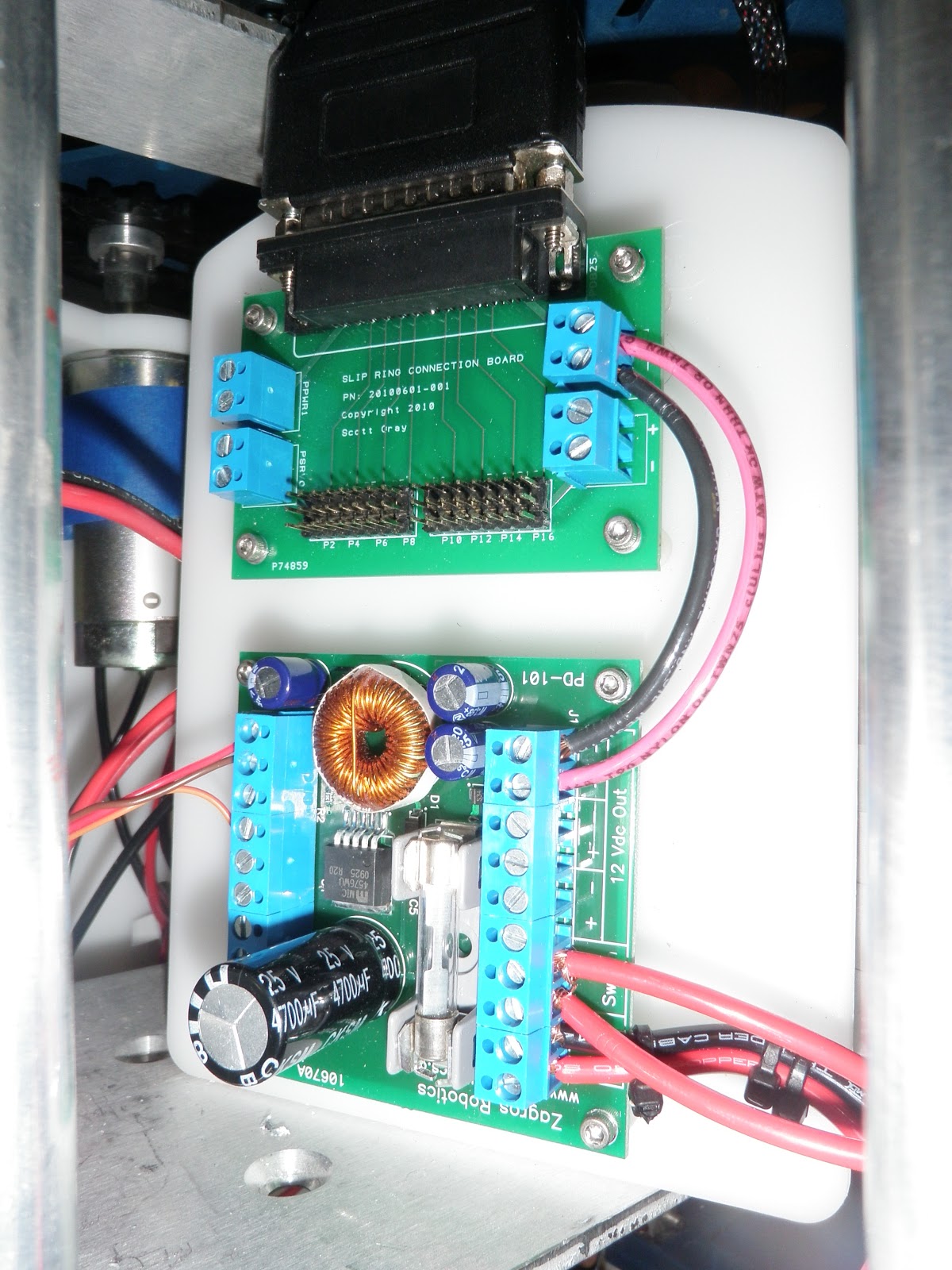
Below is the power bad annex. The board on top is the inner body slip-ring panel, and the lower unit is a power distribution board from Zagros Robotics. This power distribution board takes an input of 12 volts and steps it down to 5 ea. 5V outputs and 3 ea. 12 volt outputs. The jumpers in the upper right are taking the 12 volt signal form the power distribution board to the slip-ring board.
For those that are still awake - you might be asking ..... 12 Volt input ? I thought this was running on 24 Volts. Stay tuned to the bottom of the page for a video that will reveal a 24 Volt to 12 Volt regulator. So - I go from 24 Volt Main power to 12 Volts for various electro-goodies and then have the option for 5 Volts as well. As of now, the 5 Volt power output will power the RC receiver.
This reminds me of my first car, affectionately named "Schlomp 1". "Schlompy" was a 77 Ford LTD that had an 8 track player (and more steel in a single door than most cars on the road today). In college, I had a 8-track to cassette converter, I used this with a Cassette to CD converter for a portable CD player. I successfully spanned 25 years of audio technology in a single vehicle. Good times, good times indeed.
Back to the build. The main power bay with an additional switch in the upper left hand corner. The switch is for the Zagros Power Distribution board. It HAS to be switched - something I found out after I hooked it up and no power was coming out. Actually, the switch is optional, as I could have run a jumper between the switch inout, effectively making the board always "on". I had a couple extra switches, so I threw one on the bay board and gave it some 24 Volt juice to power the LED light in the switch..... Ya' know, as I always say "It aint cool if your chrome don't shine, and it aint less cooler if your switch don't light"

Here is a shot of the slip-ring board installed in the dome. I have been having a lot of fun with the nylon standoffs on these little boards. (It does not take much for this one, no siree, never has....)

Not only did Darrel and Heather bring lunch - they brought a little gift for R2 - his very own handy-droid tool ! He approves.

... And as promised, a little video showing off the Electronics bay/board. A virtual tour of where all the power goes. This plan started in my head, and came to reality by buying a lot of parts, and throwing them all together. I still have a MAJOR concern about the skins fitting on with all of the goodies installed. It is not a huge issue, as I have room to reconfigure the items on the cutting board, but if I don't HAVE to move stuff around, that would be very nice. Of course, I could have put the skins on to make sure all of this stuff was going to fit..... but then I would not have anything to complain about in future blogs.
And a last parting shot of the little guy

I imagine the next task will be addressing the new scooter motor holders in his feet. The casters are getting caught up within the foot shells, and causing the scooter motors to labor until the "break free". R2 does not run nearly as smoothly as he did. In the end, I know the new motor mounts will be great, but as of now, they are a step backwards in my progress. I had to tweak the Acrylic mounts before they were good to go, I just have not spent same time on these mounts.
No comments:
Post a Comment