DAY 15 - Slow to start, but finished STRONG.
Another week away from home, then off to the workshop for the weekend. Saturday welcomed me with numerous boxes of goodies that I had ordered over the pat week.
Last week during the tear down of all of the pieces-parts, I was really concerned about how the skins were fitting on the frame. I have read about a number of builders saying that they have a gap on the sides of the skins that they fill in, in one manner or another. I was happy to find that I did not have this particular issue..... Until I realized that my gap was at the bottom of the back door. Not a small gap, mind you - about 1/2 inch. The gap could be closed if you REALLY wrapped the skins tight, but there was no way that the skins were going to stay in an acceptable position without someone holding them..
Out came the grinding wheel. I imagine a good number of builders will cringe, but I took the grinding wheel to the outside of a classic JAG V4 frame, working ever so gently to remove a bit of the O.D. I figured if I removed too much material, the skins could always be shimmed from the inside. After 4 grinding sessions, and about 3 hours - the skins fit really nice. (And wouldn't you know it - no photos of the results.....
Here is a photo of everything broken down. What a pile of crapola.....

Onwards to what I REALLY set out to do today. I spent the last two weeks working over ideas on how to make a manual 2-3-2 droid. Over the past month, I bought a number of items that I thought would work, including various sizes of square aluminum tubing that would telescope up and down. Of all the ideas I tried, none of them allowed for the amount of travel I needed within the limited space inside the body.
That is, until I came up with this - linear slides and pillow blocks :

In my search for anything and everything linear / sliding / actuating, I decided to give these a try. These are rails used in CNC and router tables. The bearings inside the pillow blocks can withstand 600 lbs of weight - so I feel confident that they will be adequate for my weight unconscious friend here.
In my little melon, I devised a number of mounting plates for the center foot. Some using 80-20 aluminum, others various flanges and brackets. Thankfully - simplicity ruled the day and I could not be happier with the results.
As I have decided to run the scooter motors and dome drive at a whopping 24 volts, the first thing I needed to do was make sure the batteries would fit inside the body and still allow for retracting the center leg. The twin batteries sit nicely on the outer rim of the lower body. I plan on using some Velcro straps around the lower uprights to hold the batteries in place.
You can see the beginnings of the top and bottom aluminum plates that will be used to mount the linear slides below. The aluminum bar crossing the back near the batteries (along with the associated front bracket) needed to be notched so they would allow : A. the center foot to travel into the body. B. sit flush and double as a battery mount.

Flash forward to the completed project. The 2 screws in close proximity are for the vertical braces of the JAG frame and the others are to hold the aluminum mounting plates in place. You can't tell from this angle, but the center foot has plenty of clearance to pull into the body. (And no, the batteries were removed in this inverted state in an effort to save my toes)

Looks like someone is happy to have their new center leg installed. Either that - or he's doing his best Tricky Dick impersonation.

With the help of rudimentary photoshop rotation skills, I inverted this photo to show how the leg sits in it's retracted mode. In this state, the quick disconnect doohickeys will hold the leg in the "up" position for those two-legged glamor shots.

Here is a closeup of the disconnect. The actual part description from Amazon.com is
I found two on EBay - and picked up the others from Amazon. Apparently, I got the last two in stock.. as they are now sold out. There are four of these collars used - two in front and two in back. One to hold the leg up and the other to hold the leg in the down position for 3 wheeling.

Here is the upper bracket across the middle of the frame. The risers are used so the slide can allow enough travel into the body and have the center foot clear the bottom of the skirt. In this top bracket, I drilled 3/4" holes to allow the rail to pass through the bracket. In my online searches - I knew I wanted to use aluminum, and ordered 1/2" stock..... the frame is closer to 1/4".... if you plan on doing something like this - use 1/4" aluminum. Working with the 1/2" material was a bear.

Another angle showing the top bracket, including the 3/4" holes drilled for the rails. I have a drill press and all, but day-um - that was not fun drilling those holes. My lack of metalworking tools (and skills) really showed in this little project.

Here is the bottom bracket. The rails have tapped holes in the ends, so the bottoms of the rails are screwed into the bottom mounting plates. Here the bottom collar is left open, and the top collar locked to hold the leg in position. I like the option of having adjustable height in the "leg down" position. This was not planned, mind you, just one of those happy mistakes you run into when you have n idea what you are doing.
You can also see the notches so the mounting plate fits inside the uprights of the frame. Dad made one, I made the other. As we switched from drilling, sawing, grinding and test fitting, we passed each other 32 times between the droid and the workshop. Each and every time, the person going into the workshop muttered an inappropriate word and fired up another tool. Like I said - we have limited metalworking tools... but we make up for it with colorful language !

The bracket that is used to hold the center foot was made from a couple of 90 degree angles and a 4" X 6" aluminum plate. The angles allowed me to drop the leg below the two cross bars. I will probably reinforce the brackets across each other and from front to back, as I think this mount will take some wear and tear as he is tooling around town.

And, yes, you do have to suffer through 30 more photos of this project. It has been in my head for WAY too long, and now that it is a reality, i must share. And share. And share....

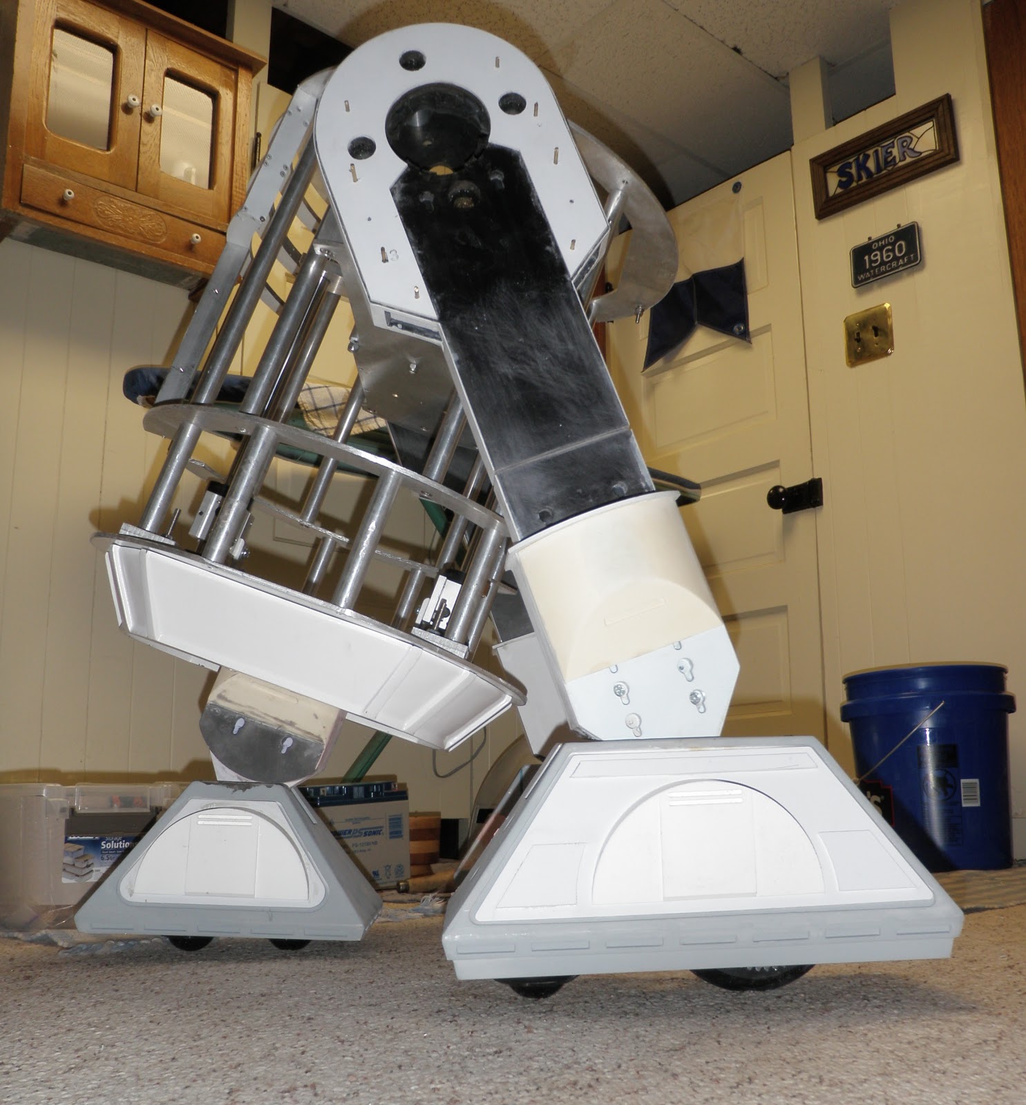
Here is a photo of the entire setup, soup to nuts. I will get a video of this in action up soon. Bad had and a questionable outfit made me think that I should wait to get in front of the camera for a demo.

A view of the entire frame with 3rd leg extended.

A view of the entire frame with 3rd leg extended... minus 12 degrees.

Another photo of the mounting bracket in case you scrolled past the previous photos when I said I was going to show this 30 more times.

Turn to the right.

Turn to the right, hold the camera straight and minus 12 degrees.
Parked in the corner, standing guard of his boxes of bolts and bits.

... And last but not least: my dome panels arrived this week. The R2 Builder's club resident master-of-all-things-resin, Crash made these beautiful Carbon Fiber dome panels.

Each of these weighs less than a potato chip, and will be placed in the appropriate place within the dome. (The thing on the floor)

Like so.

And so.

I have my work cut out for me uhhhhh, cutting out the existing panels and allowing the correct recess so the panels sit flush with the rest of the dome. Crash has posted an excellent tutorial on the Astromech boards, and I have a few ideas up my sleeve on how to accomplish this task. Ultimately, these dome panels will then open and shut.... someday.
It will be sad to paint these beauties. I plan on leaving the underside unpainted to show off a little BLING when they are opened. Alas, that day is a LONG way off, so the plan may change. Wish me luck, as tomorrow, I tear into a perfectly good looking dome... expletives included at no extra charge.
No comments:
Post a Comment