It has come time in the build to work on more electronic goodies.
For the most part, the wiring of the motors and drivers has gone really well, and I am extremely pleased with the results. I knew the day would come that I had to do some soldering on breadboards... and I was not looking forward to that day.
Over the past two weekends, I have been working on soldering and mounting the following:
- Data Port Logics
- Charge Bay Indicator
- Periscope lighting kit
Wiring = easy, soldering = well, let's just say I need some practice.
Here are some photos to show you the good and bad of the past couple of build days.
Good : A nice power distribution board from Astromech.net member Dan S. This board has a built in USB power port along with 3 ea. - 5 volt, 2 ea. - 9 volt and 3 ea. - 12 volt pass through terminals. I swapped out the usb power source I was using for the Bluetooth extender, and I am now using power directly form this board. I may hook up the USB power charger later, simply because it would be cool to charge an iWhatever off of this R2 unit.

Here is the power board mounted on the cross brace on it's own cutting board panel.

A top-down view of the Zagros robotics power distribution board (on the right), and the Club built board (on the left). It is scary to think that I may actually use all of these outputs for the various lights and shiny-blinky-bling that I am adding to this increasingly complicated metal mound.

Last weekend, Dad jumped in and worked on a mount for the Bose speaker that will be R2's voice. A simple aluminum bar was used and mounted with the screws that hold the now removed leather cover.

Dad test fitting the speaker on the mount.

... and the results are perfect !

Here is a side view of the speaker mounted within the body. I have a much better feeling with this mount as opposed to the velcro that was holding it in previously.

This little device and it's associated boards kicked my little behind for a while. With all of the wires that need to come off of the back of the light panel, it is difficult to find a place to mount the Arduino board that controls all of the random blinking of the lights. This board sits on the inside of the outer skins, and needs to have clearance with all of the the other pieces parts that are already inside the frame. It was mounted four times before it finally fit into the body. (The photo you see below is either try 2 or 3.....)
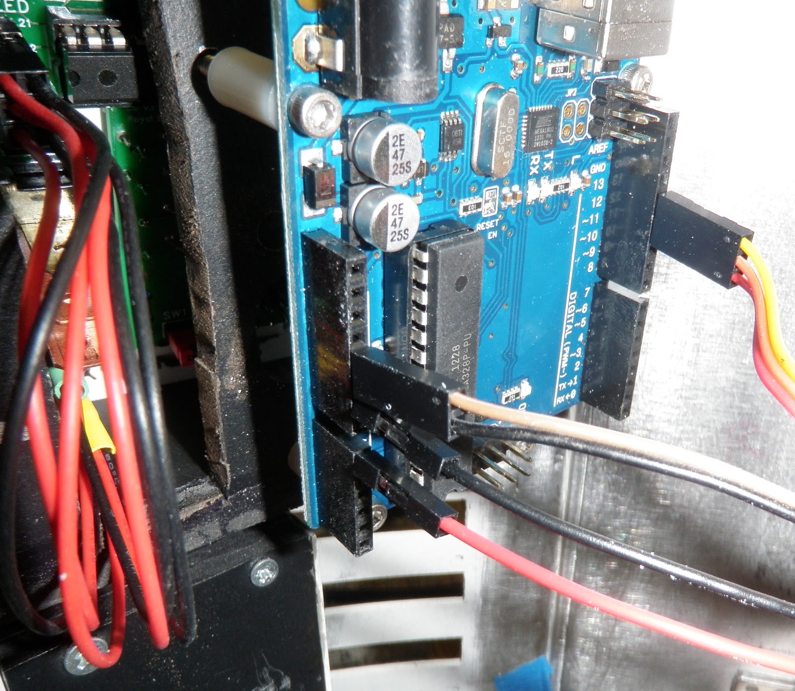
That little Arduino board runs the code for the Data Port and Power Bay lights. Completely useless in the scheme of things, but, when it is running, it looks great. What made this difficult was getting all of the wiring quick connects from the skin mounted lights to the inner body. If there is a need to service R2 in the field, and I need to pull the front skins off, I will need to disconnect all of the power easily. The Anderson Powerpoles are great little connectors, and are used ad-nauseum on this assembly.
I also opted for a switch that would turn the front panels on and off. This added some time to the project, but it looks cool, and I figure, unless he is standing still, there is no need for the lights to be running. It will also be cool for people to flip the switch and see something happen.... (IF I let them get close enough)

My new obsession - heat-shrink wire thingies. Yeah - they are really easy to use and look great to finish off connections.

Here is a shot of the Power Bay indicator. The lights below the switch are to show the condition (charge) of the battery. Currently, there is only one light lit... the red LED. I believe I will need to tweak the code on the Arduino board to get the amber and green lights to work.

On the other side of the body is the Data Port. Lots of random movement in these lights - really sweet, but again, nothing but bling. They serve no purpose other than to be cool.

Instead of waiting a couple of years to upgrade certain parts, I find myself upgrading as I build. That is upgrading AFTER I have assembled something. The dome is a prime example... fiberglass to Aluminum. Patience would be a good practice, but I am learning all the time.

The ankle cylinders were mounted in about 5 minutes and look really good.

Good luck finding the required spacer and bolt at Home Depot or Lowes..... Luckily, an Ace Hardware opened up about 5 minutes from home, and they have EVERYTHING. Ace has always been a throwback to old-school hardware stores. They have ALL of my business from this point forward. Home Depot and Lowes - you have my permission to close as many stores as you wish.

This is the bolt that will support R2 on his outer legs.

A show of what will be, and what will was.......

I also installed a battery condition meter on the back board. This meter shows the available charge left in the battery. I am not exactly sure how accurate it is, as I recently charged the batteries, and it is on Full at the moment.

This little hunk of PCB was my nemesis this weekend. As stated before, my soldering skills are lacking, and this did nothing but prove that fact. You ask - how difficult is it to solder a dozen LEDs onto a breadboard.... I asked myself that - and I was WRONG. It was a royal P.I.T.A.
As Mom and Dad headed out this afternoon, they asked what I was going to work on. My response, "Swearing at a piece of plastic and wires".

Then I shot a victory video ! Came home to find out that I did not shoot the video.... I blame a combination of frustration and elation on the fact that it actually worked for not noticing that the REC light was, in fact, not blinking. I will get a video of this gem with next weeks update.

All of the wiring and PCB will fit inside the periscope housing below.... another task that I am not looking forward to. The good thing is that once it is in place, it does not need to come out (unless my crappy soldering rears it's ugly head).

More of something next weekend.... I am at the point that I have a TON of stuff going on in this build. The past two weekends were really thin on the victories, and long on the process. Hopefully I will return to my old form in the upcoming weeks.
No comments:
Post a Comment